- SPS technical coordination web site
- BE-OP SPS section (SPS homepage, SPS wiki and SPS white board)
- eLogBook: External and Internal.
- Vistars
- Jorg Wenninger's web site (SPS operation, Training for operation)
- PS & SPS & AD users' schedules
- SPS status week by week (from the coordinators): 2009, 2010, 2011.
- Some drawings (CERN Drawing Directory Server: CDD):
- SPS complex schematic layout: spslm___0002.pdf
- SPS complex transfer line valves sector: spsvcpeb0133.pdf
- Vacuum chambers of SPS and transfer lines: spsvcpeb0108-vAA.pdf. The diameter of the SPS vacuum chamber outside magnets is most of the time 159 mm (externally, and 156 mm internally), as it is the case for instance near COLDEX.41737.
- SPS complex ring valves sector: spsvcpeb0132.pdf
- SPS sextant 1 LSS1: spslnins0049-vAE.pdf
- LSS1 schematic layout from QF11410 to QF12210: spslnins0051-vAH.pd
- SPS standard periods parameters: spslnins0050.pdf.
- LSS5 from QF51410 to QF52210.
- SPS ring and transfer lines photographs: Site 1 and 2.
- SPS optics:
- PS-SPS Complex Optics Pages (by O. Berring).
- Twiss parameters from MADX in 2009 at extraction (but without the extraction bumps, which are given below) at both the centre and exit of the elements:
- LHC: centre and exit. The tunes are (Qx=26.13, Qy=26.18).
- CNGS: centre and exit. The tunes are (Qx=26.62, Qy=26.58).
- SFTPRO: centre and exit. The tunes are (Qx=26.66, Qy=26.58). The horizontal tune Qx=26+2/3 is used to extract the beam during a slow extraction.
- SPS apertures (the most critical case is 14 GeV/c with the CNGS beam after capture):
- Considering both betatronic and dispersion contributions in the beam size: SPSaperture_BetaAndD, SPSaperture_BetaAndD_SortedInX, SPSaperture_BetaAndD_SortedInY.
- Considering only the betatronic contribution in the beam size: SPSaperture_BetaOnly, SPSaperture_BetaOnly_SortedInX, SPSaperture_BetaOnly_SortedInY.
- Therefore:
- The horizontal bottleneck is the TIDP.11434: ~ 3.9 SX (horizontal beam size) considering both betatronic and dispersion contributions, or ~ 5.5 SX considering only the betatronic contribution. The physical horizontal aperture is APER_1 = 41 mm. Note that the minimum physical horizontal aperture is reached at the TCSP.51934 (30 mm), but due to the small horizontal betatron function, this is not the horizontal bottleneck.
- The vertical bottleneck is the TIDV.11892: ~ 3 SY (vertical beam size). The physical vertical aperture is APER_2 = 20.4 mm. Note that the minimum physical vertical aperture is reached at the TIDP.11434 (15 mm), but due to the small vertical betatron function, this is not the vertical bottleneck.
- Apertures' pictures:
- Whole SPS: X alone (in blue), Y alone (in red), X and Y.
- Sextant 1: X (zoom), Y (zoom), X and Y (zoom).
- Sextant 2: X (zoom), Y (zoom), X and Y (zoom).
- Sextant 4: X (zoom), Y (zoom), X and Y (zoom).
- Sextant 6: X (zoom), Y (zoom), X and Y (zoom).
- 6 sextants (superperiods): Location of the SPS periods and superperiods, SPS cross section and SPS ventilation.
- A typical SPS cell is composed of the following elements: QF-MBA-MBA-MBB-MBB-QD-MBB-MBB-MBA-MBA (Picture including the pumping ports). The length of a 1/2 cell is 31.9977 m and the length of a cell is 2 times larger, i.e. 63.9954 m. There are 18 cells per superperiod and 6 superperiods (sextants) in total, i.e. there is 108 cells in total.
- 1st 1/2 cell: QF-MBA-MBA-MBB-MBB (example).
- 2nd 1/2 cell: QD-MBB-MBB-MBA-MBA (example).
- Example of SPS optics from MADX (LHC450): Betas and Dispersions. The length of a sextant is equal to 18 times 63.9954, i.e. 1151.9172. The total length of the SPS is equal to 6 times 1151.9172, i.e. ~ 6911.5 m.
- Maximum horizontal dispersion in the SPS: ~ 4.5 m in 4-12-24-32.
- Maximum horizontal and vertical betatron functions in the SPS: ~ 107 m.
- Minimum horizontal and vertical betatron functions in the SPS: ~ 20 m.
- Bends (744 in total, 18 tons / dipole, ~ 6.7 m length / dipole):
- MBA (360). There are 2 MBA per half cell except in 14, 16, 17, 18, 19 and 21 (i.e. 2 times 30 times 6 in total). The vertical half height is 19.25 mm (dimension when compressed in the magnets).
- MBB (384). There are 2 MBB per half cell except in 16, 17, 18 and 19 (i.e. 2 times 32 times 6 in total). The vertical half height is 25.75 mm (dimension when compressed in the magnets).
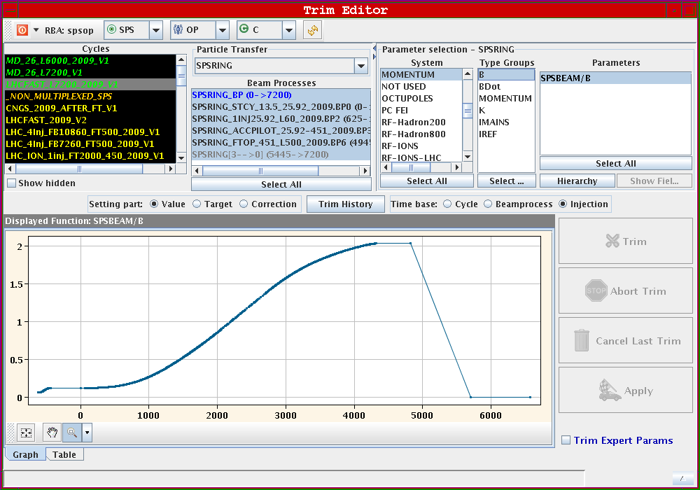
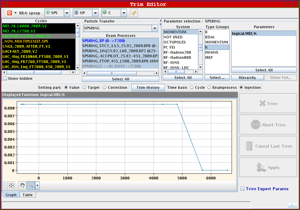
- At 450 GeV/c, the magnetic field reaches 2.03 T and the current in the mains ~ 5780 A: Picture 1, 2, 3, 4 and 5.
- The maximum gradient is 22 T/m.
- The bending angle from each bend is 2 Pi / 744 = 8.4 mrad.
- Beam-based SPS magnets' shims adjustment after magnets change in the SPS => Example oat 31/08/2010:
- 3 new carbon-coated MBB magnets have been installed in the machine in positions 51470, 51490 and 51530. A fourth MBB magnet, without carbon coating, was moved from position 51490 to position 51550. Beam-based measurements were performed afterwards to check the horizontal orbit at top energy and it was decided to remove some shims of the magnet MBB.51470, which was too strong by ~ 0.28% (the too long magnetic length was converted to a mechanical length to be removed).
- The method is the following:
- Measure the horizontal orbit at top energy and ask for a correction with the minimum number of correctors and using the most efficient one(s) => YASP said that we need a correction of + 24 microrad on the MBB.51470.
- Assuming that all the 744 bending magnets give each an average bending angle of 8.4 mrad, it means that the magnet MBB.51470 is too strong (due to the positive sign required) by 24/8400 ~ 0.28%. This corresponds to a delta (B lmag) / (B lmag) = delta lmag / lmag = 0.0028 as the magnetic field did not change.
- Jeremie Bauche then uses the following calibration between the magnetic length lmag and the mechanical length lmech: 1.5 mm for lmech corresponds to 2E-4 of delta lmag / lmag.
- Applying the previous calibration to our case leads to an excessive mechanical length of 18.6 mm, which has then to be removed.
- In fact they removed 19.5 mm and it was said from the CCC that only ~ 1/2 of the job was done which means that either there is a factor ~ 2 missing in the calibration (Jeremie thinks it should be good within ~ 20-30 %) or there is a problem with the procedure to have a fully quantitative understanding.
- Max betaX = QF = Even number (18 / sextant, from 0 to 34). 10 tons / quad. 18 times 6 = 108 quads QF, which are spaced by a betatron phase advance of 90 deg: the tune should therefore be ~ 108 / 4 = 27 (which is the case...). Some modifications:
- Sextant 1: QFA.11610 and QFA.11810.
- Sextant 2: QFA.21610 and QFA.21810.
- Sextant 3: Nothing special.
- Sextant 4: QFA.41810.
- Sextant 5: AP.DO.QF5141 (following QF.51410) and AP.DO.QF5161 (following QF.51610).
- Sextant 6: QFA.61810.
- Max betaY = QD = Odd number (18 sextant, from 1 to 35). 10 tons / quad. Some modifications:
- Sextant 1: QDA.11710 and QFA.11910.
- Sextant 2: QDA.21710 and QFA.21910.
- Sextant 3: Nothing special.
- Sextant 4: QDA.41710 and QDA.41910.
- Sextant 5: AP.DO.QD.519 (following QD.51910).
- Sextant 6: QDA.61710 and QDA.61910.
- Extraction bumps (data):
- CNGS => East extraction bump (zoomed). The maximum of the horizontal bump is ~ 34.2 mm at QFA.41810 (at the monitor BPCE.41801 it is ~ 32.7 mm).
- LHC => Both East extraction and West extraction bumps (zoomed), only the East extraction bump (zoomed) and only the West extraction bump (zoomed). The maximum of the horizontal east bump is ~ 39.8 mm at QFA.41810 (at the monitor BPCE.41801 it is ~ 37.8 mm). The maximum of the horizontal west bump is ~ 34.3 mm at QFA.61810 (at the monitor BPCE.61805 it is ~ 33.5 mm).
- SFTPRO => North extraction bump (zoomed). The maximum of the horizontal bump is ~ 49 mm at QFA.21610 and the minimum is reached at ~ QF.22010 with ~ -34.3 mm.
- Note that there are no injection bumps.
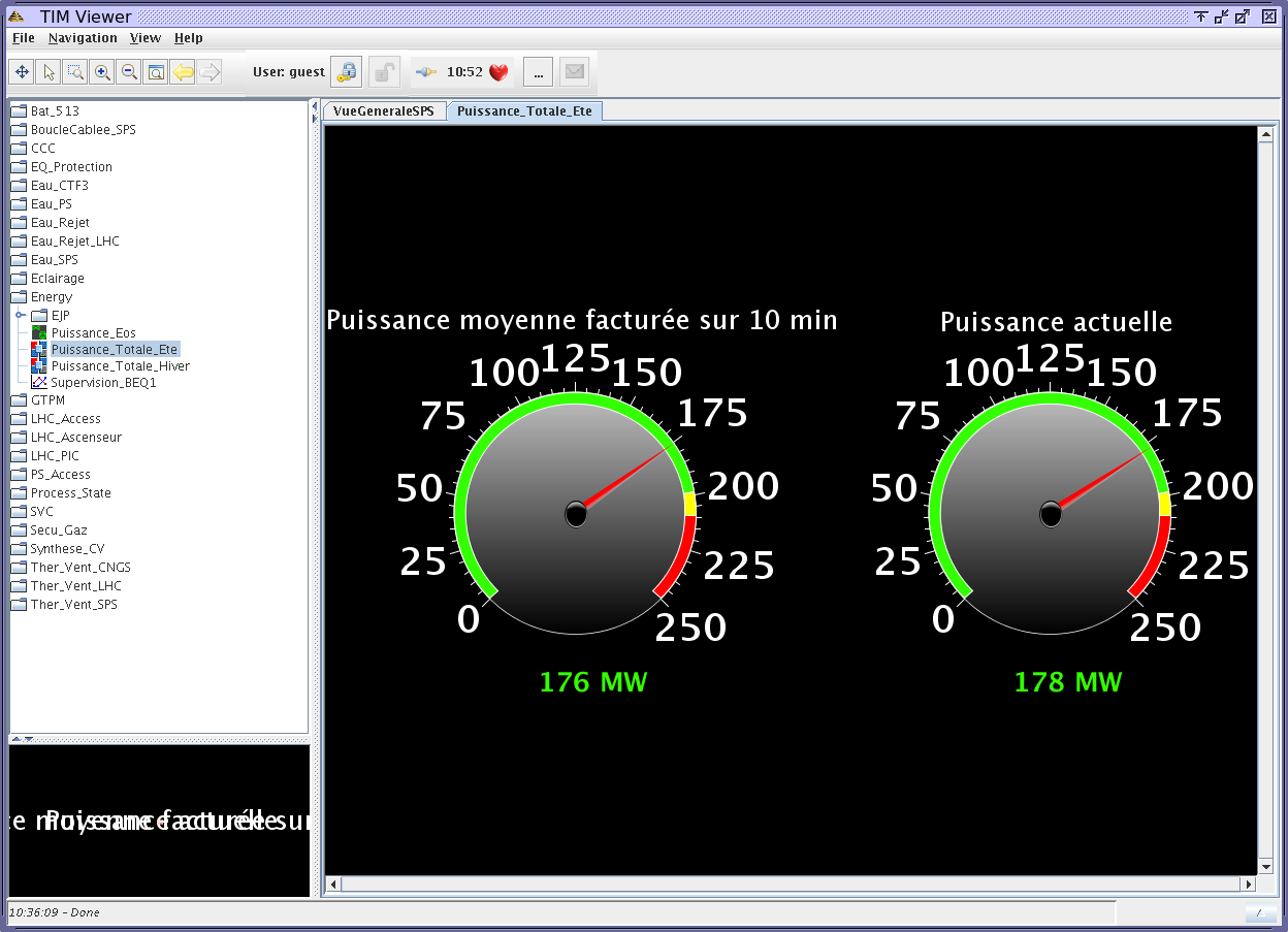
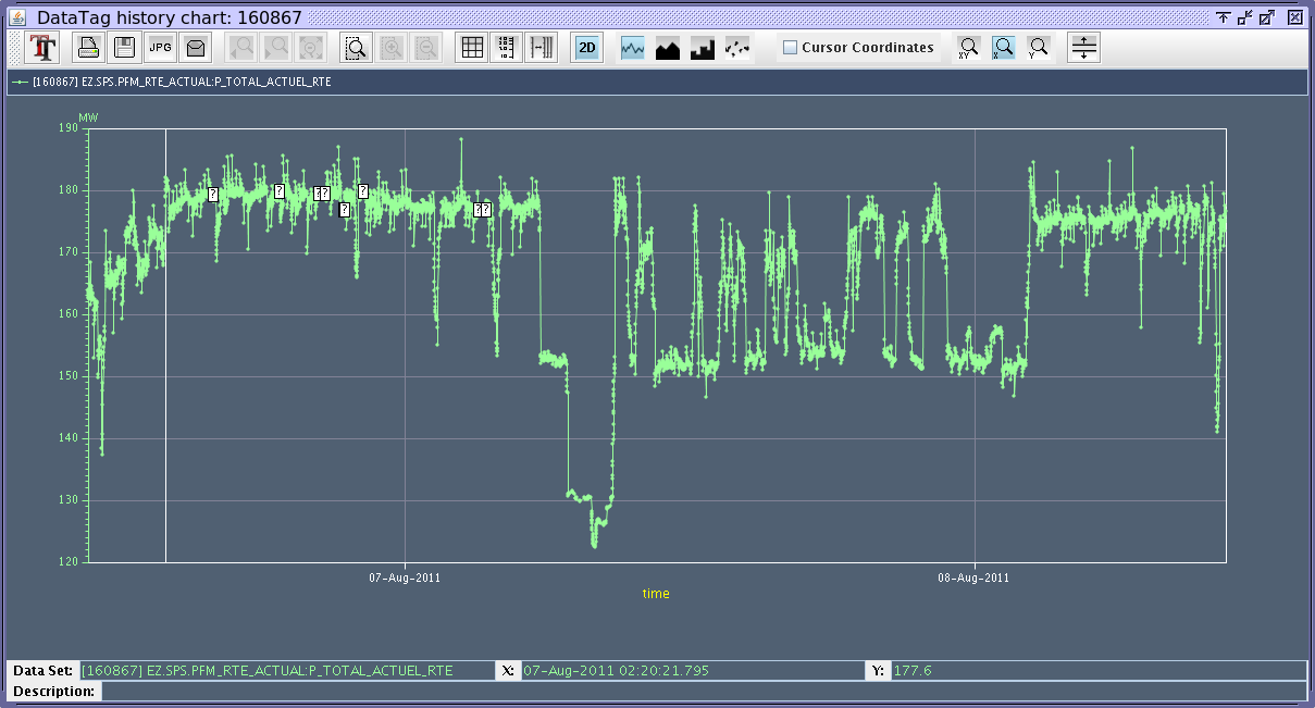
- Energy consumption (to see for instance if the SPS pulsed or not) => Example for the case of Sunday 07/08/2011
- SPS Control / General Services / TIM Navigator.
- Energy / Puissance_Total_Ete => Gives the "Puissance moyenne facturee sur 10 min" and "Puissance actuelle": Picture1.
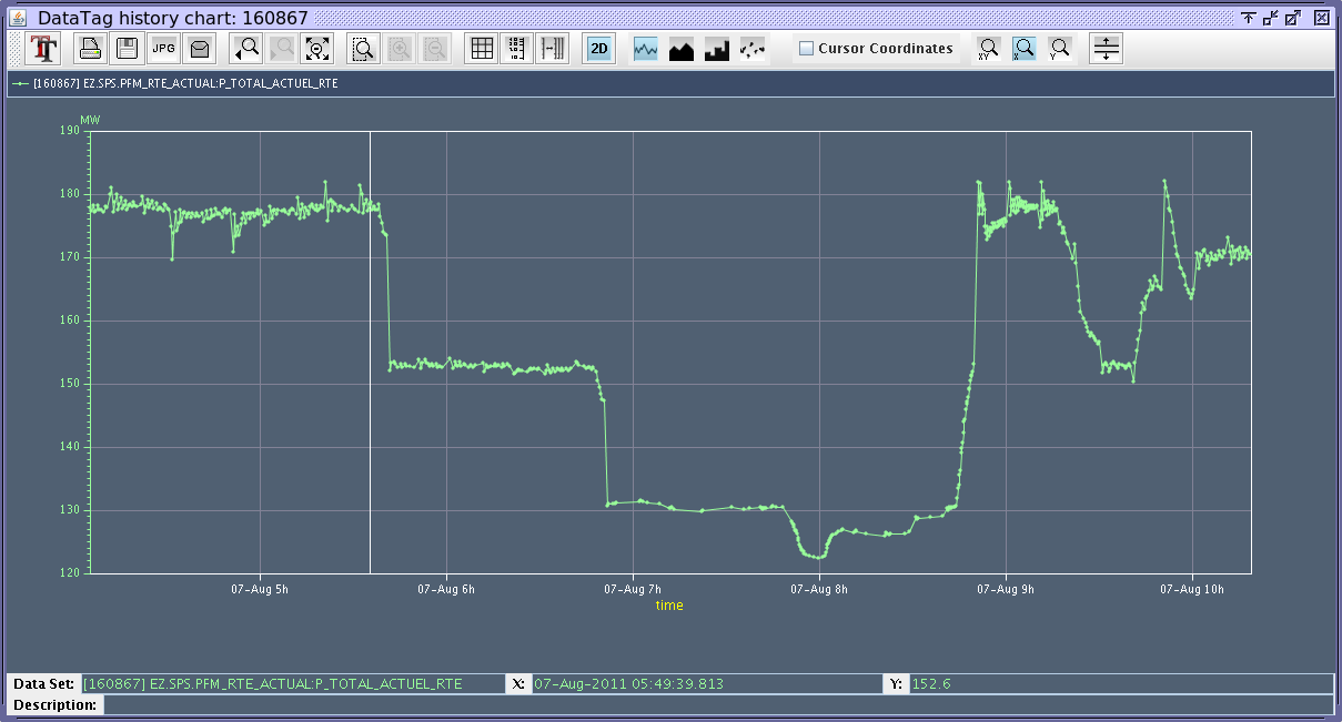
- Right click on "Puissance actuelle" / Charts / New Chart.
- Click on the get data from last 2 days / Chart => Gives the evolution of the power over the last 2 days: Picture 2 and 3.
- In this particular case, the SPS did not pulse between ~ 06:45 and ~ 08:45.
- YASP:
- SPS re-alignment at the beginning of each year (displacements of quads):
- 2009:
- QF.10410: 0.8 mm, QF.12610: 0.3 mm, QF.32010: -0.7 mm, QF.516: 0.3 mm.
- QD.13110: -0.35 mm, QD.22910: -0.45 mm, QD.31910: 0.25 mm, QD.53310: -0.35 mm.
- 2010:
- QF.32010: -0.32 mm, QF.33410: 0.48 mm, QF.52010: -0.64 mm.
- Computation of the required quads' displacements from orbits' corrections using YASP.
- 2011 (on Monday 14/02):
- QF.13610 (in fact it is QF20010): -1.54 mm, QF.21810: -0.59 mm, QF.33010: 0.65 mm.
- QD.23110: -0.4 mm, QD.42710: -0.46 mm, QD.51510: -0.73 mm, QD.6130: -0.84 mm.
- In addition, during the morning we will check the horizontal aperture we seem to have in 218. To inject all the beam the OP team had to do a bump (inside the machine) of - 22 mm => See reminder below, as the enlarged quad in 218 (QFA.21810) was modified during the shutdown.
- Reminder on all the magnets which were foreseen to be changed during the shutdown (list from Jeremie Bauche sent on 21/12/2010) => 8 magnets:
- Position 10570 => Magnet MA 098 (MBA).
- Position 10650 => MA 353 (MBA).
- Position 12770 => MA 159 (MBA).
- Position 13510 => Q 018 (QD).
- Position 20010 => Q 143 (QF).
- Position 21810 => QA 100103 (QFA).
- Position 51510 => Q 167 (QD).
- Position 62510 => Q 179 (QD).
- Furthermore: Certains quadrupoles largis prsentent des dfauts de calage avec des amplitudes importantes de mouvements des bobines. Celui en position 21810 devra d'ailleurs tre remplac. Nous avons prvu d'ajouter des coil retainers sur tous ces aimants pour empcher que la situation ne continue se dgrader.
- SPS injection screen references:
- Whenever the MKP kicker is not pulsing, then the MDSH.119 must be pulsing to correctly dump the injected beam on the TBSJ (injection dump). The link to the MDSH is through the MKP interlock system.
- Dumped beam positions: on the screen 1199 the beam should be in the center with the MDSH on, i.e. when the kicker is on STANDBY or OFF (power - not timing!). Note that the screen is inverted, the ring is on the right!
- On BTV1197, beam position for LHC beams (26 GeV/c) => With the injection kicker ON: The beam is injected when the spot is on the left, i.e. on the left vertical trace (of the three vertical lines).
- Losses on the flat bottom:
- Of MDs for instance, around 4200 ms => Due to the servo spill which is not ppm! => put it OFF with the EquipState.
- At some other times => Could be due to large spikes in the orbit correctors.
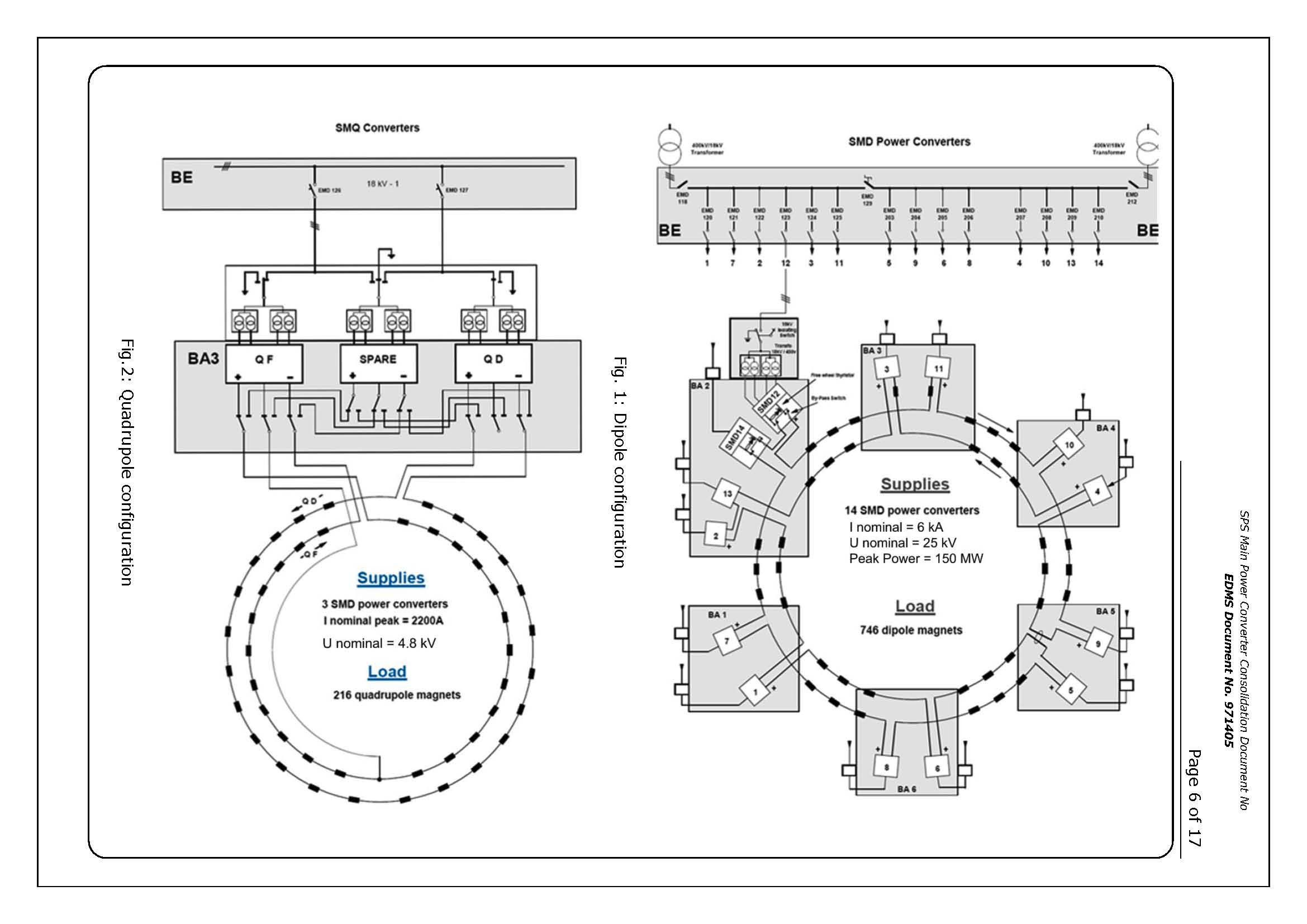
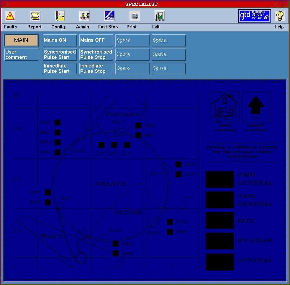
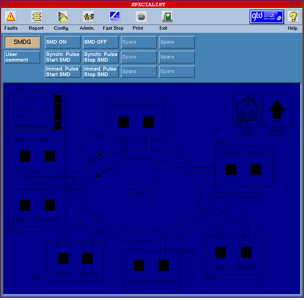
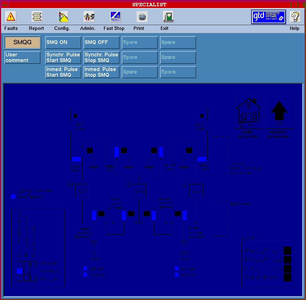
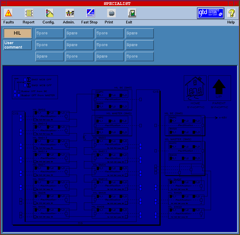
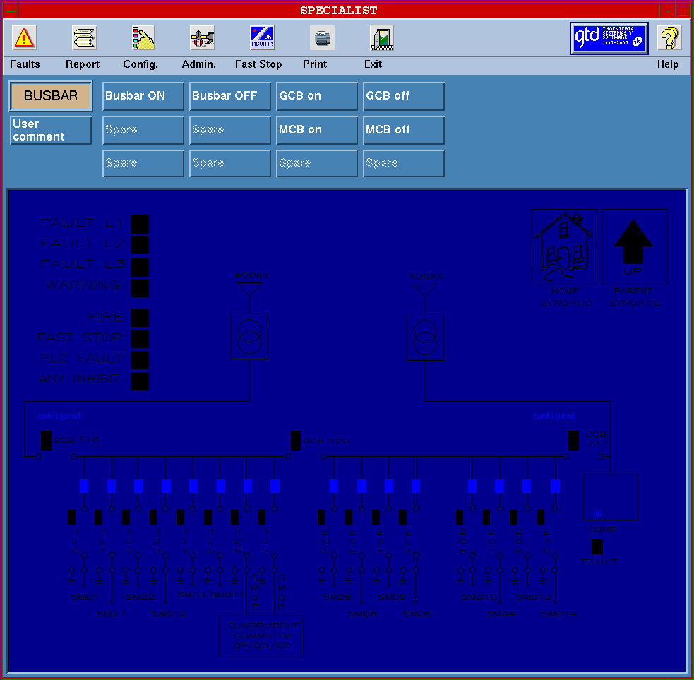
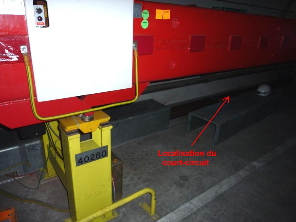
- SPS Main Power Converters: Picture 1 (there are always 12 stations in service and 2 spares), 2, 3 (at BA5 there are DCCTs on each side and the difference in current is measured. If there is a "delta I" it means there is either a shortcircuit between the 2 busbars or a ground default. The next step is then to locate the default, isolating each sector), 4, 5, 6.
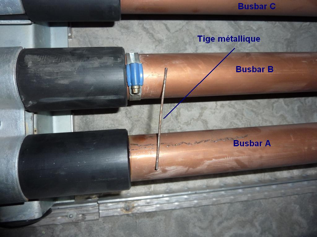
- Busbar issue on 22/03/2010: Picture 1 and 2.
- SPS RF course by T. Bohl (2007).
- SPS frequency: Switch from LHC to local.
- SPS injection phase adjustment (looked at on OASIS): The 1st discontinuity comes from the phase (to be adjusted with the RF MMI program => Injection phase). The possible 2nd slow drift comes from an energy error.
- Beam Quality Monitors:
- SPS. Reminder from Giulia Papotti: The SPS BQM expects all 4 timing events for the possible 4 injections in the long LHC cycles (LHCx cycles). If any of the timing events are missing, then the acquisition is not correctly setup and we will get a warning message similar to 'ADC readout problem, data not valid'. Consequently the beam dump will be pulled. So, in case we want to inhibit some of the injections by removing the repetition (RPT = 3) in the Working Sets / MTG events, remember to disable the BQM in Fabio's GUI and to mask it in the SIS. Nb: For the LHCFASTx cycles, only one injection is expected.
- LHC.
- BPW observation with OASIS mode d'emploi.
- SPS RF cavities:
- 4 at 200 MHz: ACTA.31637, ACTB.31739, ACTC.31836 and ACTD.31934.
- 2 of 5 sections; 2 of 4 sections; 1 section has 11 cells.
- Total voltage = 8 MV.
- The limit in RF power for LHC beams (as it is not a continuous beam) is ~ 1 MW, whereas it is ~ 0.7 MW for CNGS/FT beams due to the fact that these beams are continuous.
- To obtain more voltage and reduce the beam loading, it was proposed to rearrange the existing 200 MHz TW RF system in the SPS (http://Paf-spsu.web.cern.ch/paf-spsu/meetings/2010/m21-01/SPS%20RF%20upgrade.pptx). Due to the peculiar nature of the 200 MHz RF cavities (TW), adding cavities reduces the impedance!
- 2 at 800 MHz: ACL.31695 and ACL.31733.
- SPS kickers:
- MKP: Some possible problems. Use the Expert program KITS (under Windows or in the CCM => SPS MKP Expert Control) to set the User Permit.
- MKD (H and V): Below 37 GeV/c the beam is dumped horizontally on the TIDH and above ~ 100 GeV/c the beam is dumped vertically on the TIDV.
- MKQ
- MKE
- FMCM (Fast Magnet Current change Monitor): Some possible problems.
- FEI (Fast Extraction Interlock):
- The ROCS FEI system is implemented as a task in the SPS ROCS PC front-end crates (FESA class). The task is triggered by a CTIM associated to the fast extraction.
- Often we have to update the FEI settings after optimization of the transfer lines TT40/TI8 and TT60/TI2. The method is the following:
- Open the application under SPS Control / SPS Beam Interlocks / SPS Extraction PC Interlocks.
- File / Cycle Selection => Choose cycle and LHCB1 Transfer if we want to start with Beam 1.
- Click on LHCB1.
- Click on FEI<>LSA (which compares the FEI current settings, which is a table in the database on LSA, with the LSA settings of the selected context, which is another list on LSA corresponding to what we actually trim) => It found which equipments are out tolerance. Be careful that by default the tolerance cut is 75% and that one needs to change this value to say 10% to really see the changes.
- If there are some differences, select the equipments (only some of them will be change depending on the role) and click on Settings >> FEI.
- Click on Trim All References and that's it!
- Redo the same thing with Beam 2, starting by changing the cycle...
- SPS to LHC extraction display since 2011: example when everything is fine (green).
- Settings copy to copy the LHC transfer lines from one cycle to another:
- Open the application under SPS Control / SPS Beam Control / Settings Copy.
- Click on the cycle (whose setting one wants to copy on another cycle).
- Click on LHC/CNGS Transfer Steering Copy.
- Click on LHC Transfer.
- Click only on the destination cycle one wants.
- Finally click on Copy and that's it!
- RBI81607 operation (CNGS and or LHC).
- BIC (HW interlocks) and SIS (Software interlocks):
- Case of 26/07/10:
- Chromaticity measurements:
- Can be done automatically (on LHC-type beams, above transition) with the "SPS Auto Q" program using "Auto Q'" => Example on LHCFAST2 in 06-02-2009.
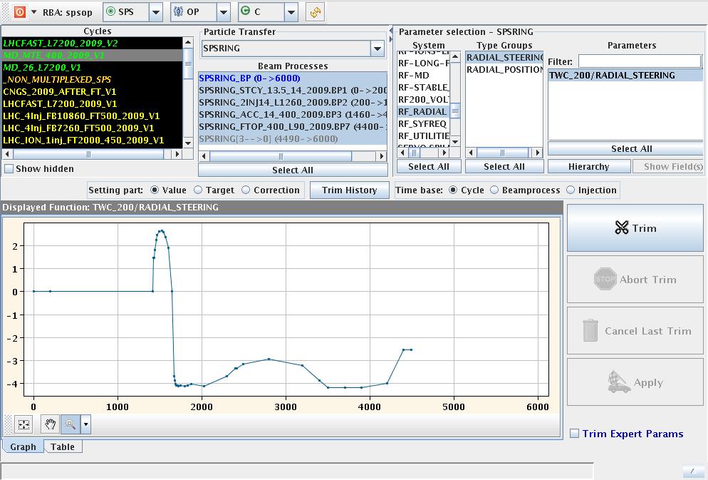
- However, for SFTPRO-like beam (as also CNGS, i.e. injecting below transition) the automatic measurement does not work well and in addition the radial loop is active only after 1230 ms (at 1230 ms we switch from the synchro loop to the radial loop, as we have to cross transition at ~ 1485 ms) => A manual measurement needs to be performed from ~ 1240 ms to ~ 1500 ms (i.e. just after transition). Reminder: Both transverse chromaticities should be set to ~ -0.1 below transition and ~ +0.1 above transition. Manual measurement (done by performing radial steerings with the Trim Editor of -2 mm, 0 mm and +2 mm, and measuring the tunes with the Qmeter) => Example on CNGS2 (MTE) on 29-03-2010 and RFsteering for 0 mm.
- Coupling between the different machines (to be entered in the CBCM) => More explanations.
- SPS batch spacings for the different LHC beams.
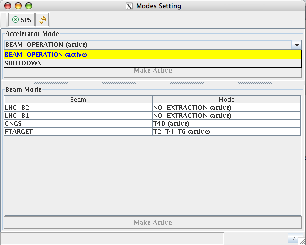
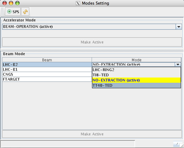
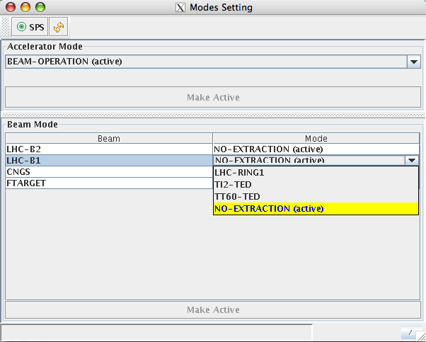
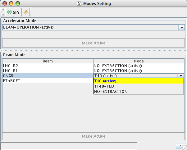
- Accelerator Mode: Picture 1, 2, 3, 4 and 5.
- SPS Users timings: 2008, 2009, 2010, 2011.
- EquipState:
- SPSRING
- CNGSTransfer (CNGS_Target_Cumul2009)
- Orbit issues and faulty magnets or SMD issues:
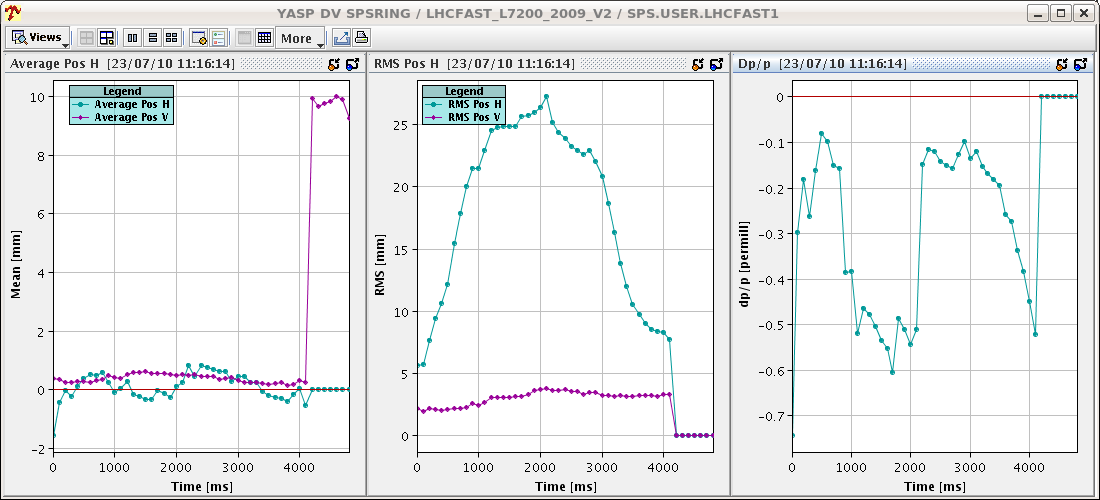
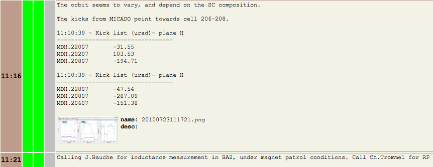
- Case of FR 23/07/10: Picture 1, 2 and 3. The kicks from MICADO point towards cell 206-208. J. Bauche went to do an inductance measurement in BA2 (under magnet patrol conditions, calling Ch. Trommel for RP) and he confirmed that there was a problem with the magnet MBB.20750 which needs to be replaced.
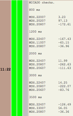
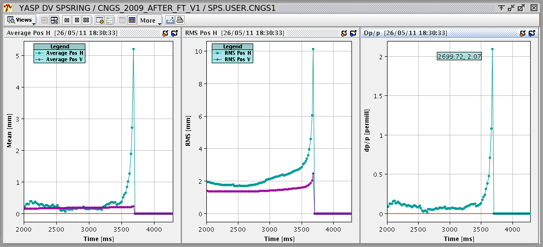
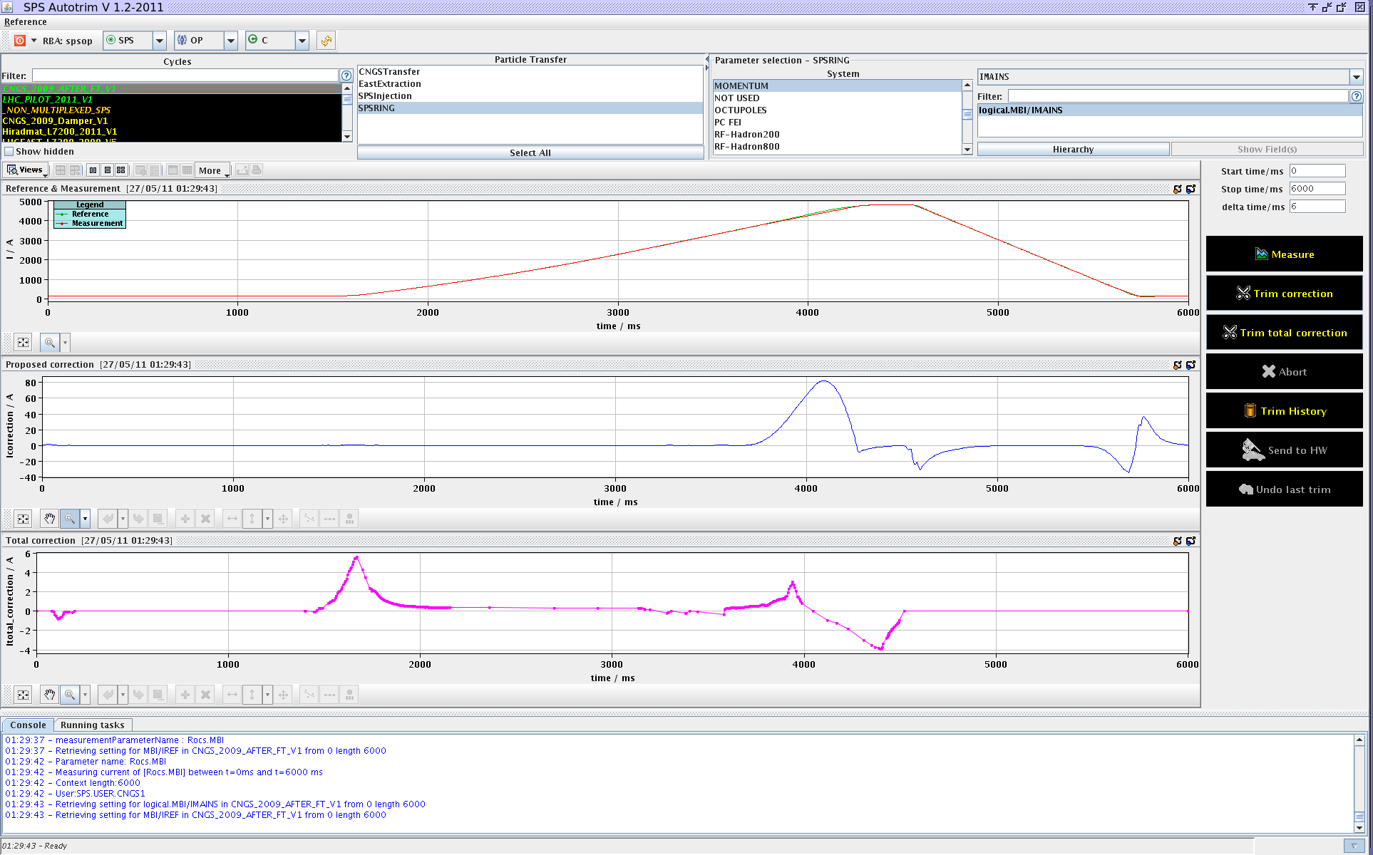
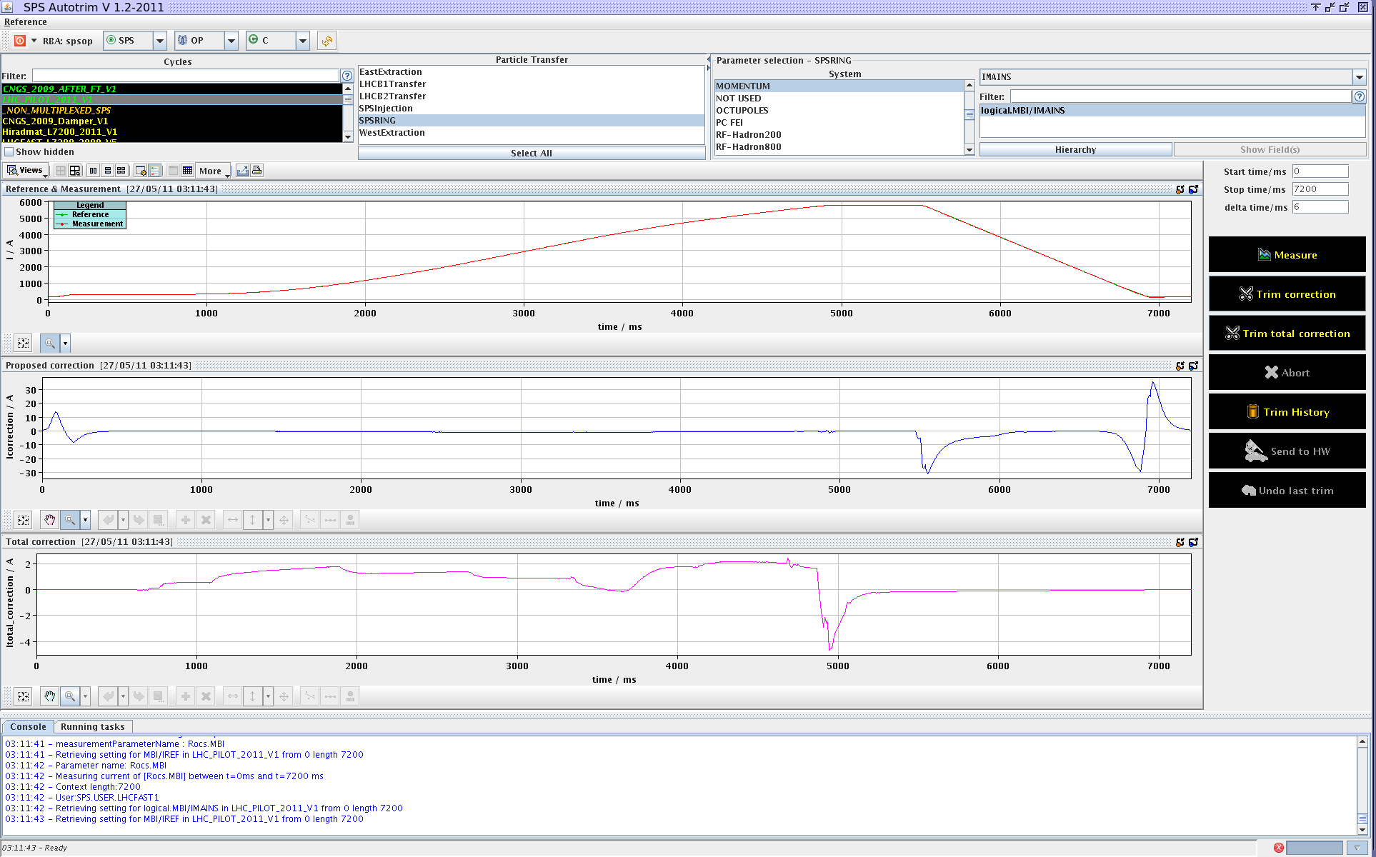
- Case of FR 27/05/11: The beam was lost on CNGS at ~ 3700 ms (with large rms measured in H: Picture 0) whereas the beam on LHCFAST was OK. The pb was due to a missing reference on SMD3 => auxillary power supply of the card sending the reference which was down. This could be seen looking at the Autotrim: Picture 1. For the LHC it is not observed (see Picture 2) as the ramp is slower.
- Correction of the horizontal coherent oscillations at injection (if the Autopilot is not working or if the MOPOS for instance have to be disconnected as it is the case when we have the ultimate LHC beam):
- We measured the transverse emittances (on 02/06/2010) and had to correct the coherent oscillations at injection (not using the Autopilot as the MOPOS did not work, but using the 2 orthogonal correctors BPH120 and BPH122) => The Hemitt decreased from ~20 to ~ 5 microm. Reminder on the procedure to correct the coherent oscillations at injection: Optimize 1 then optimize the 2nd and then redo it several times.
- Vacuum interlocks:
- When there are 2 (or 3, tbc) ionic pumps (not anyone, but specific ones placed at certain locations in the sector) which trip (which can happen for a pressure smaller than 1E-4) and a vacuum gauge above 1E-5, this for 63 ms (for the medium gauge, but there are also slow and fast ones), then there is an interlock which cuts the beam and the sector valves close to isolate the sector.
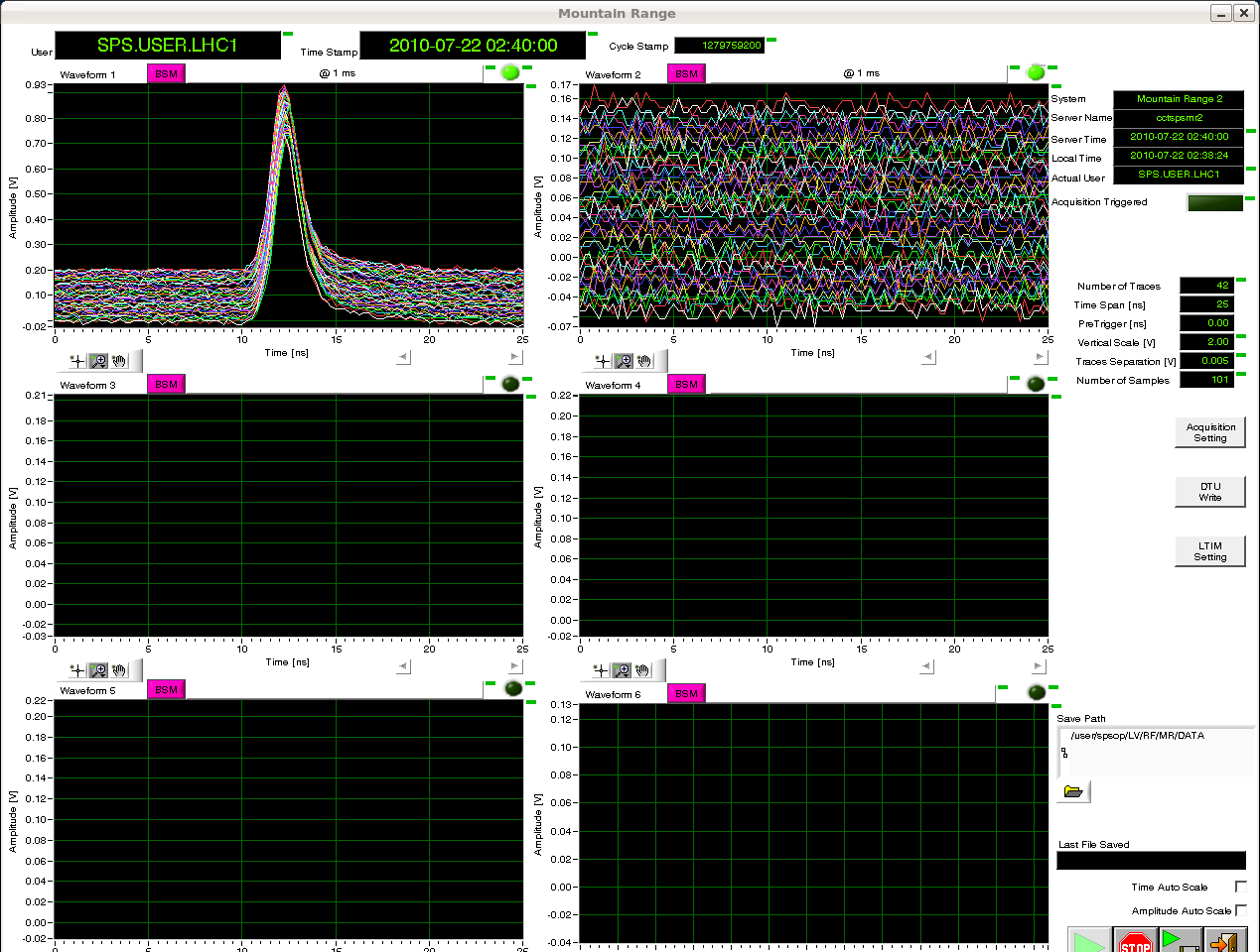
- BSM (Bunch Shape Measurement):
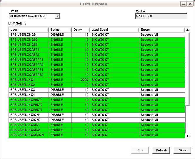
- Bunch length meas. from the CCC on 21/07/10 => Adjusted the Delay at 2020 to meas at 2000 ms as it is with respect to a timing at -20 ms before injection => Picture 1, 2 and 3.
- Mountain range and BSM adjustments.
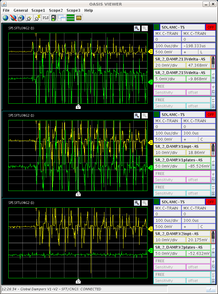
- Transverse dampers:
- PUs used for the transverse dampers: 12 PUs are shared between the RF (for transverse dampers) and BI: 204 - 215. RF works at 120 MHz and BI at 200 MHz. 204 - 207 are used for LHC since ~ 2001 and shared with BI. It is done in the surface with a hybrid to split in 2, 1 for RF and 1 for BI. Wolfgang Hofle needs a perfect delay (adjusted at 26 GeV/c) between the 2 H PUs: 204 and 206. The same is true between the 2 V PUs: 205 and 207. These PUs are used for LHC. For FT we use the PUs 212 - 215. The PUs 208 - 211 are spare ones.
- Jeremie Fleuret's talk on 11-06-2010. The Delta signals are not normalized. There are 2 gains: the 1st to adjust wrt intensity and the 2nd (in LSA) to adjust wrt energy. The fact that it uses 120 MHz is due to the ecloud issues. In practice, we should aim for a damping time of ~ 0.5 ms. If it is too fast then we dont have a good tune measurement anymore.
- Example of a case on SA 22/07/10 when the damper V2 did not seem to produce any signal (Picture). Driver amplifiers were on for the DC power supply but the RF was not on. Input signal present, no signal on the deflector plates. A local reset on the driver amplifiers did not work. After switching of level 2 (and 3) locally and switching on again the fault disappeared. No alarms were visible, the Ua power supply also had no faults. Next time, call the power piquet.
- Another example on SU 23/07/10: The beam was completely lost after the second injection on the SFT and CNGS beams just after a sequence change. The beam was lost ~200 turns after the second injection. With only an injection the beam went fine...A transverse coherent instability was suspected (may be due to a problem with the transverse dampers) and we decided first to check the effect of the chromaticities (increasing them by ~ 0.4 in both planes). The second injection entered better and the beam was accelerated. The RF ll piquet was called as the transverse dampers were suspected, which was right => Comment by R. Louwerse: Damper H1 did not work. After investigation in BA2 it was found that the power amplifier has a fault at the level of the bias current of the tetrodes. Tube A is ok, tube B has an unstable bias current. The Ua power supply tripped on overcurrent on output 2. A reset from the CCC was not possible because of the ECA hanging. No communication with the MMI possible. After a local reboot of the ECA the MMI works. A transient on the amplifier that tripped may have caused the ECA to hang. On Saturday V2 had a driver problem: may be linked to this. Pushing the UG1 for tetrode B to 156 V cleared the fault, now Ug1 is back to 91 V. If the fault repeats, call the power piquet. A tunnel acces may be needed. For the operators: If H1 trips more gain is needed on H2 (6 dB) but this may create an overload. Try to reduce the injection errors as much as possible.
- Instrumentation:
- BCT (Beam Current Transformer): BCT.11601 and BCT.31832 (for high intensities) and BCT.41436 (for low intensities).
- BFCT (Beam Fast Current Transformer):
- BFCT.11640, BFCT.31450, BFCT.41438 and BFCT.60903.
- BWS: TransverseEmittancesComputation and BWScalibrationUsingOrbitBumpsBySCCIn2009.
- Rotational Wire Scanner (6 m/s): BWS.41420, BWS.41677, BWS.51995.
- Linear Wire Scanner (1 m/s): BWS.51731, BWS.52171.
- In the application we can play with the gain but if it not sufficient there is also a filter which can be changed under the EquipState (STEP in the ring): 0 = no filter, 1 = filter. Since 2011: If you want to put a filter go to Equipment Control--> Beam Instrumentation and open BOSTEP. Choose BTV50s in devices and select bwsf.51995. You can put a filter increasing position by one step. There are 7 filters. For filter 1 set 1 and so on...
- BIPM: IntroductionAndHWhistory(JK) and SPSmeasurementsIn2007(EM).
- BIPMH.51634 and BIPMV.51734 .
- BLM:
- BLM.11740 was moved before the MKDV1 during the 2009-2010 shutdown due to a hot spot found on the MKDV1.
- BPM: The application to do the MOPOS calibration has been added to the CCM: SPS Control > SPS Equipment Control > MOPOS Online Calibration.
- HEADTAIL monitor => BPCL.42171.
- Orbit bumps can be done in YASP and also in coasts but it has to be done on the pulsed cycle and on the flat top (it will be propagated to the coast cycle) => Usually it is better to send it by steps...
- Movable devices:
- Momentum scraper: TIDP.11434. Its main role is to scrape the uncaptured particles with lower momenta, this is why it is located inside the machine. The minimum position, corresponding to the TIDP out, is 0 mm. The maximum position, corresponding to the maximum position of the TIDP in the beam (moving from inside), is 33 mm.
- LHC horizontal collimator prototype (installed in 2004): TCSP.51934. It will be removed during the 2009-2010 shutdown and replaced by a new prototype with BPMs integrated. Furthermore, there will be also a SLAC (rotatable) collimator which should be installed at some point in 2010, close to this location (for aperture reasons, it should be upstream of the TCSP.51934 before QD.51910). In fact its position could also be optimized wrt to a possible crab cavity and the present collimator.
- Scraper (for transverse tail scraping for clean LHC injection): FunctionalSpecification(GAandHB), SPSmeasurementsIn2007(HB) and TalkHB_28-05-09.
- The scraper is BSHV.51659.
- The primary collimators are: BRCV.51899 and BRCH.51902.
- The secondary collimators are: BRCZ.52102 and BRCZ.52105.
- There are some plans to replace the copper jaws (of 3 cm) by graphite ones (of 1 cm) to reach higher intensities. Another possibility under study is to replace the scraper by a fixed collimator and make a bump around.
- News in 2010: Manual, First tests and graph before shielding from Karel.
- Controlled transverse emittance blow-up on LHCFAST2 => http://wikis/display/SPSOP/Blow+Up+Transverse:
- Last update (28/07/10): The blow-up parameters cannot be trimmed ppm. Only the timing knob for ON/OFF is ppm.One could play with the duration if it becomes necessary. A ppm version with new hardware is being planned together with BE-RF-CS section (Andy):
1) Switch off the blow-up.
2) Verify the orbit at the time of the blow-up is good, must be < 2 mm rms (H/V). If the rms orbit is large the probability that the beam does not go close enough through the center of the octupoles is high and then the blow-up does not work correctly.
3) If orbit found ok, check that the tunes are nominal at the time of the blow-up, and correct if necessary. Tunes should be checked with blow-up off using the Q-meter with kicking the beam.
4) Switch on the blow-up. The blow-up does an excitation around the tune frequency, octupoles are ramped to create more tune spread. If tune is wrong, or orbit is bad then it will not work properly.
5) Only after verification (steps 1-4) the operators should touch the knob for the amplitude of the excitation. If they touch the amplitude in a situation when the tunes/orbit are wrong and then the tunes come back to normal, you may get too much blow-up.
Currently the blow-up is connected to dampers H2 and V1. The power system of these dampers has to work properly and they must be on. Currently one tube on damper H1 is blocked, Eric Montesinos' team needs to change this amplifier. This should be done as soon as possible. H1 has now less gain (kick voltage) and this is why I connected earlier this week the blow-up to H2 instead of H1. Earlier this week the situation was not optimal due to the H blow-up connected to the faulty H1.
For the 1 to 4 bunches the transverse injection damping is off in the SPS, so the emittance also depends on having reasonable injection oscillations. As we do not have a peak hold circuit in the SPS damper it is not very effective for injection oscillation damping of single bunches (would require a test to quantify this statement).
- In 2010 there were some changes compared to 2009 => New names for the timings (SX. RF7-7-5 for H and SX.RF7-8-5 for V). Some pictures: 1, 2, 3, 4, 5, 6. Reminder: Connect (Remote Desktop Connection) to computer = abpc11659, User name / password = damper / BlowUp10.
- APCtalk_14-11-08, PAC09paper(ControlledTransverseEmittanceBUintheSPS) and some results in 2009: CTEBUin2009 and ElogBook on 24/11/09.
- Controlled longitudinal emittance blow-up on LHCINDIV (to go usually from a full bunch length of ~ 1.2 ns to ~ 1.7 ns and a longitudinal emittance from ~ 0.3 eVs to ~ 0.6 eVs) => http://wikis/display/SPSOP/Blow+Up+Longitudinal:
- It can be put ON/OFF with only 1 timing: SX.RF6-5-6 (pLHC noise extraction gate start).
- Then, when it is ON, we can play with the amplitude by:
- Connecting (Remote Desktop Connection) to computer = cerntsab35, User name = CERN\spsop (usual password).
- Opening the program "Noise Interface With Table", which is at \\cern.ch\dfs\Departments\AB\Groups\RF\Machines\SPS\LabView\LabView8\Arbitrary Function Generator E33250A\Noise Generation.
- Changing the Amplitude (the first knob in the Applic) by step of 0.005 (sending the value!) and measuring the bunch length at extraction to see when we reach the required value
- SPS Physics cycles:
- SFT_LONG_2009_V1.csv => For NA (North Area) FT (Fixed Target) experiments (13 BP = 15.6 s). Some references.
- CNGS_2009_AFTER_FT_V1.csv => Cern Neutrinos to Gran Sasso (5 BP = 6 s). Some references.
- Reminder: CNGS closed <=> Shielding plugs closed and Shutter opened and CNGS access <=> Shielding plugs opened and Shutter closed.
- Comparison between LHC (nominal), CNGS and SFTPRO: Evolution of the FBCTs (Movies under Windows Only!).
- Some installations for experiments in the SPS:
- BBLR:
- The SPS wires a grouped into 2 sets:
- BBLR1 (fixed, installed in 2002): BBLR.51760 + BBLR.51771 (the power supply is BBLR.5176M).
- BBLR2 (vertically moveable, installed in 2004): BBLR.51772 + BBLR.51774 (the power supply is BBLR.5177M).
- Some MD results in 2008: G. Sterbini's talk at the APC held on 16-01-09.
- Ecloud:
- 514: 3 pairs of antennas.
- 517: Two C-magnets (MDPH.51753 and MDPH.51754): one for exchangeable samples, with different coatings and one spare.
- 518:
- 1: Detector XSD1 (MDHW.51832) with stainless steel screen and collector as a reference.
- 2: Cleaning enamel electrode.
- 3: Detector XSD2 (MDHW.51836) with TiN coated screen (seems the TiN was in fact never there) and collector.
- 4: Detector EcEx (MDHW.51838) with electrode and collector (R. Macek type).
- 5: Detector SDNEG (MDHW.51853) with NEG coated screen and collector, surrounded from both sides by two other NEG coated chambers with two baffles. These chambers could be baked (activated).
- The magnets with the e-cloud monitors are 4 dipoles: MDHW.51832, 51836, 51838, 51853, all with 0.12 T (MDHW.51832 with 25 A). In addition, there is a C-magnet (MDPH.51753 with 28.5 A, in series with MDPH.51754 to compensate) which contains a sample which can be inserted and removed. They should be masked in the SIS when they are ON.
- 2 coated MBB magnets in 515: MBB.51530 and MBB.51550 (MBB.51570 was uncoated during the 2009-2010 shutdown).
- 1 coated MBB magnet in 514: MBB.51490 => Was uncoated during the 2009-2010 shutdown.
- M. Jimenez' talk at APC held on 16-01-09.
- SEM-CLOUD applic (SPS Control / SPS Beam Measurements / SPS e-cloud SEM):
- SEMCLOUD1:
- Channels 0-46 => XSD1 - St. Steel Chamber.
- Channels 48-95 => Neg-coated chamber.
- SEMCLOUD2:
- Channels 0-46 => Quad. chamber.
- Channels 48-95 => XSD2 - Neg-coated chamber.
- UA9 (crystal collimation): Picture 1, 2 and movie 3.
- CESAR:
- We measure the profiles at the 3 targets with CESAR (one can do the 3 at the same time on 3 different consoles) => SPS Control / SPS EA Control / CESAR GUI. Then Click on T6 for instance (same thing for T2 and T4) and then click on Profile and choose the Start (23), the End (29) and the step (0.2). The measurement equipment here is a wire that moves (step motor) by 1 step at each supercycle (i.e. it takes a long time), and at each step the wire integrates the total current. Typical beam sizes (total width at the bottom of the profiles) are:
- T2: ~ 1.5 mm in H and 3 mm in V.
- T4: ~ 2.5 mm in H and 2 mm in V.
- T6: ~ 2.5 mm in H and 2 mm in V.
- SPS ACCESSES:
- Access points:
- BA1, BA2, BA3, BA4, ECX4, CNGS, TAG42, BA5, ECX5, BA6, BA7, TT61, BA80, BA81, TCC8, ECN3.
- MIS chains => Description of the SPS access chains:
- MachineInterlockSystem => Red means OK for beam (not OK for people) and Green means not OK for beam (OK for people).
- chain 1: Prevent beam injection and circulation in the SPS.
- 2: Prevent beam extraction in LSS4 after the
TED.400354.
- 3: Prevent beam transfer in TI8.
- 4: Prevent beam extraction in LSS6 after the TED.6103.
- 5: Prevent beam transfer in TI2.
- 6: Prevent beam transfer in TT41 to CNGS. The MBG.410147 is the RBI.816 and there is a special procedure for it depending on the operation (RBI.816 operation).
- 9: Prevent beam extraction in LSS2 after the TBSE.2106.
- 10: Prevent beam transfer in TT20 to TCC2.
- 7, 8, 11, 12, 13, 14, 15, 16.
- SPS Transfer Lines:
- TT2.: seq.
- TT10: seq.
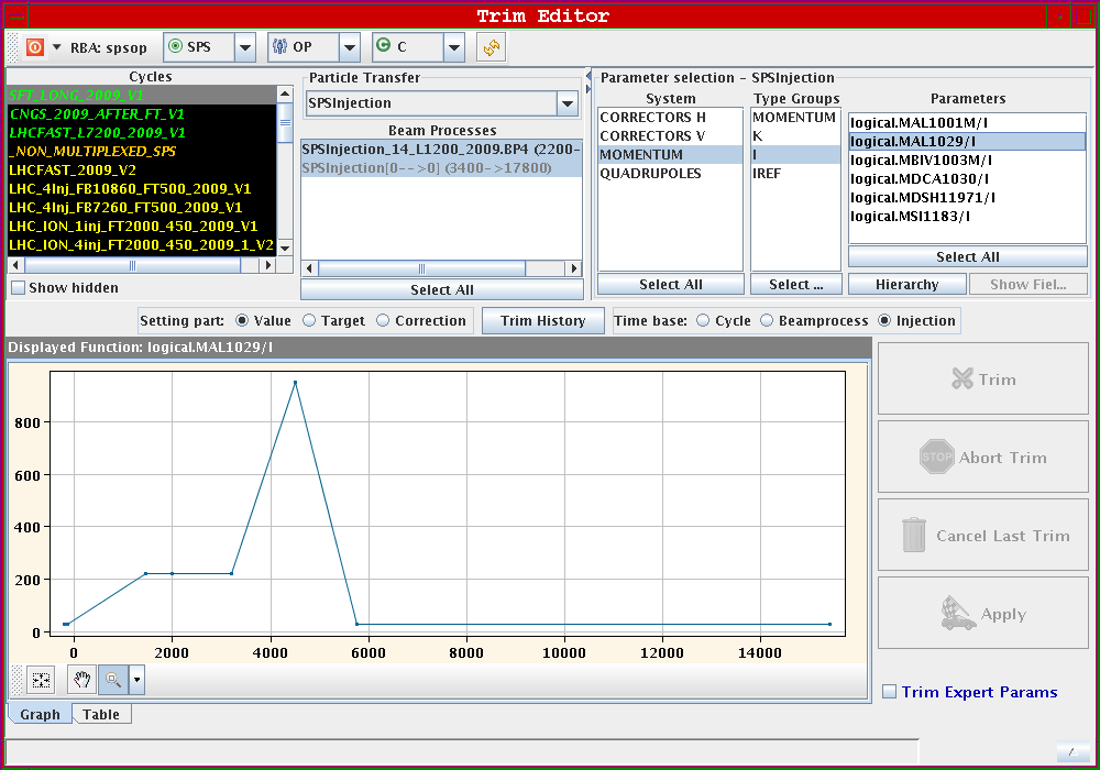
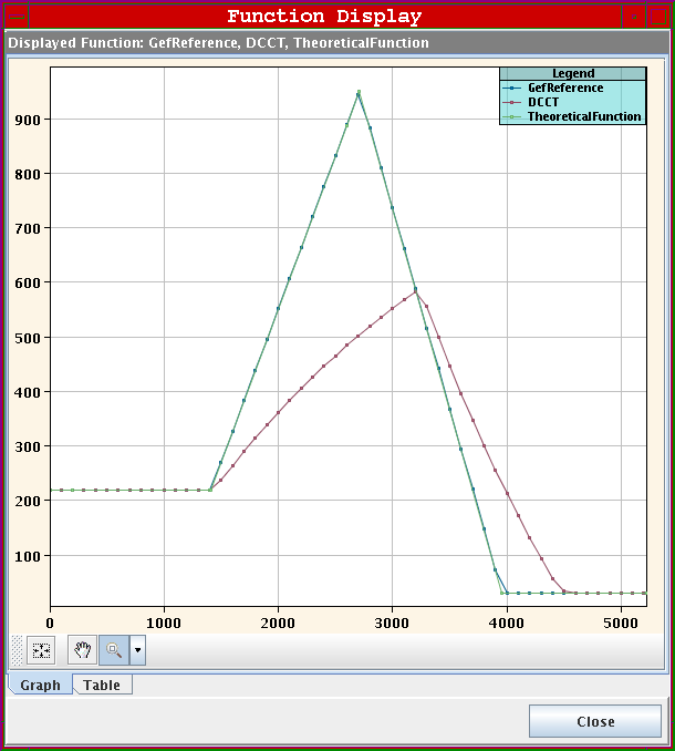
- Delay of 2 s of TT10 since 2009 to allow the "ppmization" of the SPS as there are some power supplies which are very slow and need ~ 2 s.
- MAL1029 is one of them. In fact, it even does not follow the reference (picture 1 and 2).
- There are 5 OTRs: TT10.BTV.100123 (digitalization is not working and cannot be used), TT10.BTV.101871, TT10.BTV.102454, TT10.BTV.102541, TT10.BTV.102642.
- There are 3 BTVs: 1001, 1003 and 1029.
- TT20:
- Seq.
- NA61 is complaining about the spill, which is not flat enough. Karel reminded us (09/08/10) that the beam is moving on the splitter (due to the extraction in momentum) and therefore the energy of the particles extracted is changing and we could put a slope on the energy of the line to compensate that (there is a knob for this).
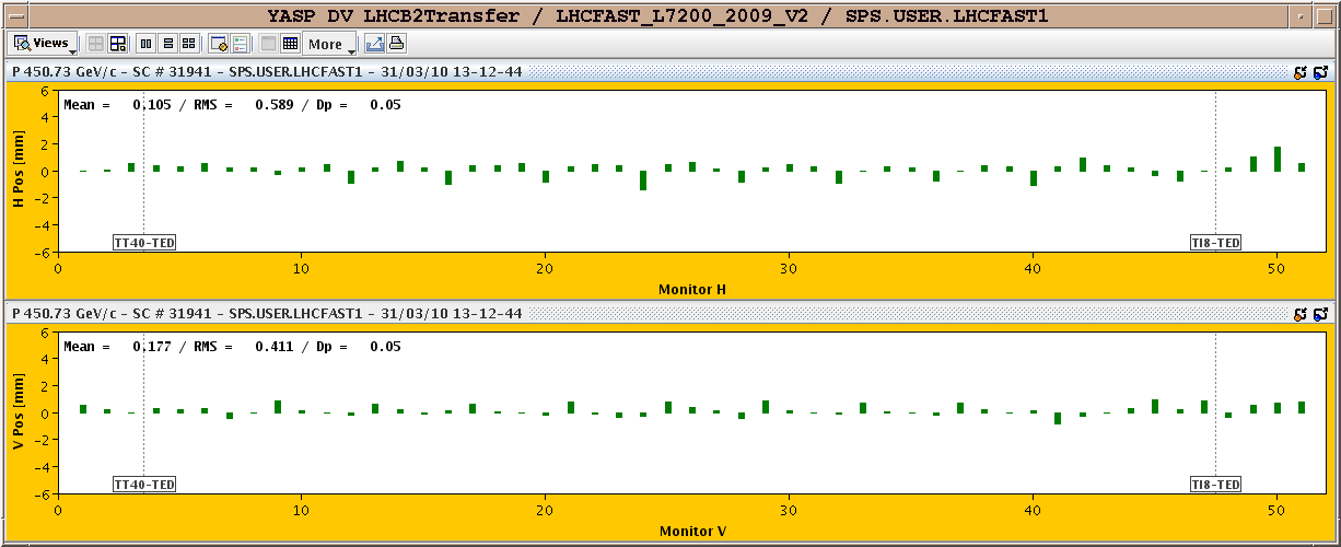
- TI2: Seq and LHCB2Transfer. The TT60-TED is TED.610321 and the TI2-TED is TED.29133.
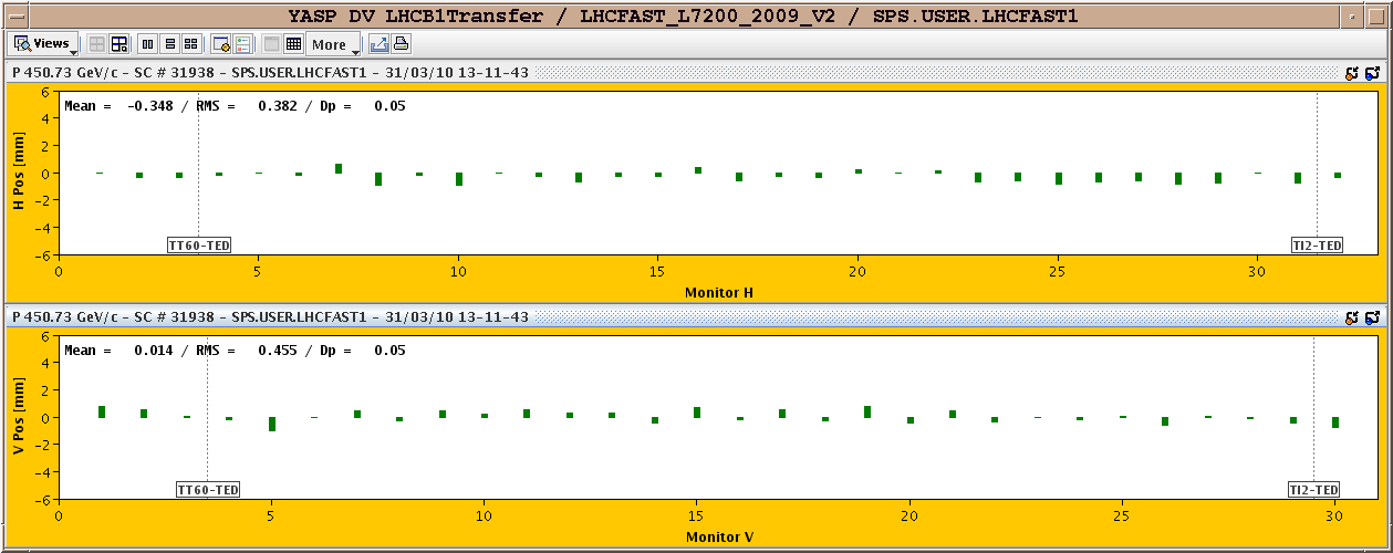
- TI8: Seq and LHCB1Transfer. The TT40-TED is TED.400354 and the TI8-TED is TED.87765.
- North Area:
- Repartition des aimants et des alimentations: https://edms.cern.ch/file/1062808/3/MagnetBibleComplete-2010.pdf.
- NA accesses: https://edms.cern.ch/file/844971/4/North_Access_2009.pdf.
- NA experiments: http://indico.cern.ch/getFile.py/access?contribId=23&sessionId=11&resId=1&materialId=slides&confId=70866.
- The wobbling is used to define the energy of the particles of interest (as a spectrometer). On H8 and H6, the wobbling defines exactly the energy as there are only 2 bends (tbc) whereas on H4 and H2 there is an additional bend and we can vary the energy.
- Goliath is one big magnet used on H4.