Minutes of the LRFF Task Force
5th meeting on Tuesday 17/04/2012 (09:00-11:00 max, 6-R-018)
LRFF members: Alessandro Bertarelli (AlessandroB), Alexej Grudiev (AG), Benoit Salvant (BS), Elias Metral (EM), Fritz Caspers (FC), Giuseppe Bregliozzi (GB), Hugo Alistair Day (HD), Jose Miguel Jimenez (JMJ), Marco Garlasche (MG), Mike Barnes (MB), Olav Ejner Berrig (OB), Oleksiy Kononenko (OK), Oliver Aberle (OA), Ralph Assmann (RA), Raymond Veness (RV), Rhodri Jones (RJ), Roberto Losito (RL), Sergio Calatroni (SC), Stefano Redaelli (SR), Vincent Baglin (VB), Vittorio Parma (VP), Wim Weterings (WW).
Present/Excused: AlessandroB, AG, BS, EM, FC, GB, HD, JMJ, MG, MB, OB, OK, OA, RA, RV, RJ, RL, SC, SR, VB, VP, WW, Pierre Strubin, Federico Carra.
1) Comments on the last minutes + Actions
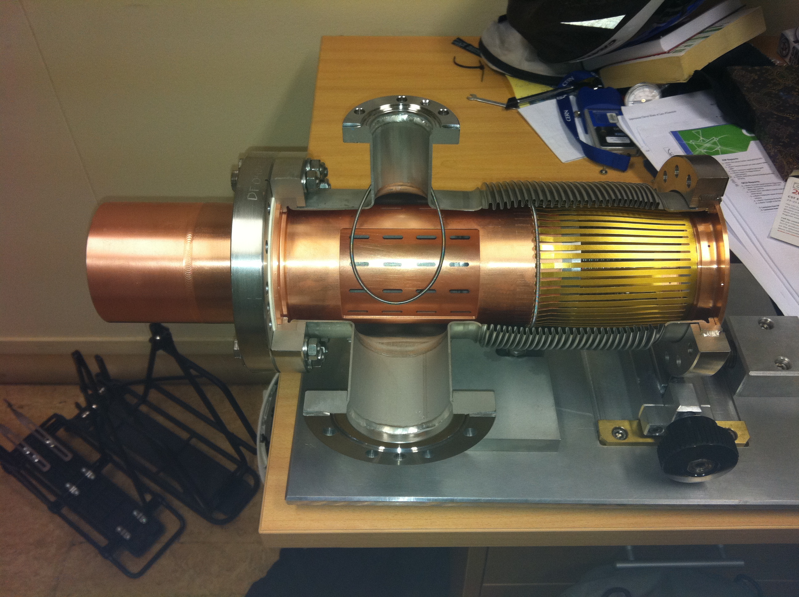
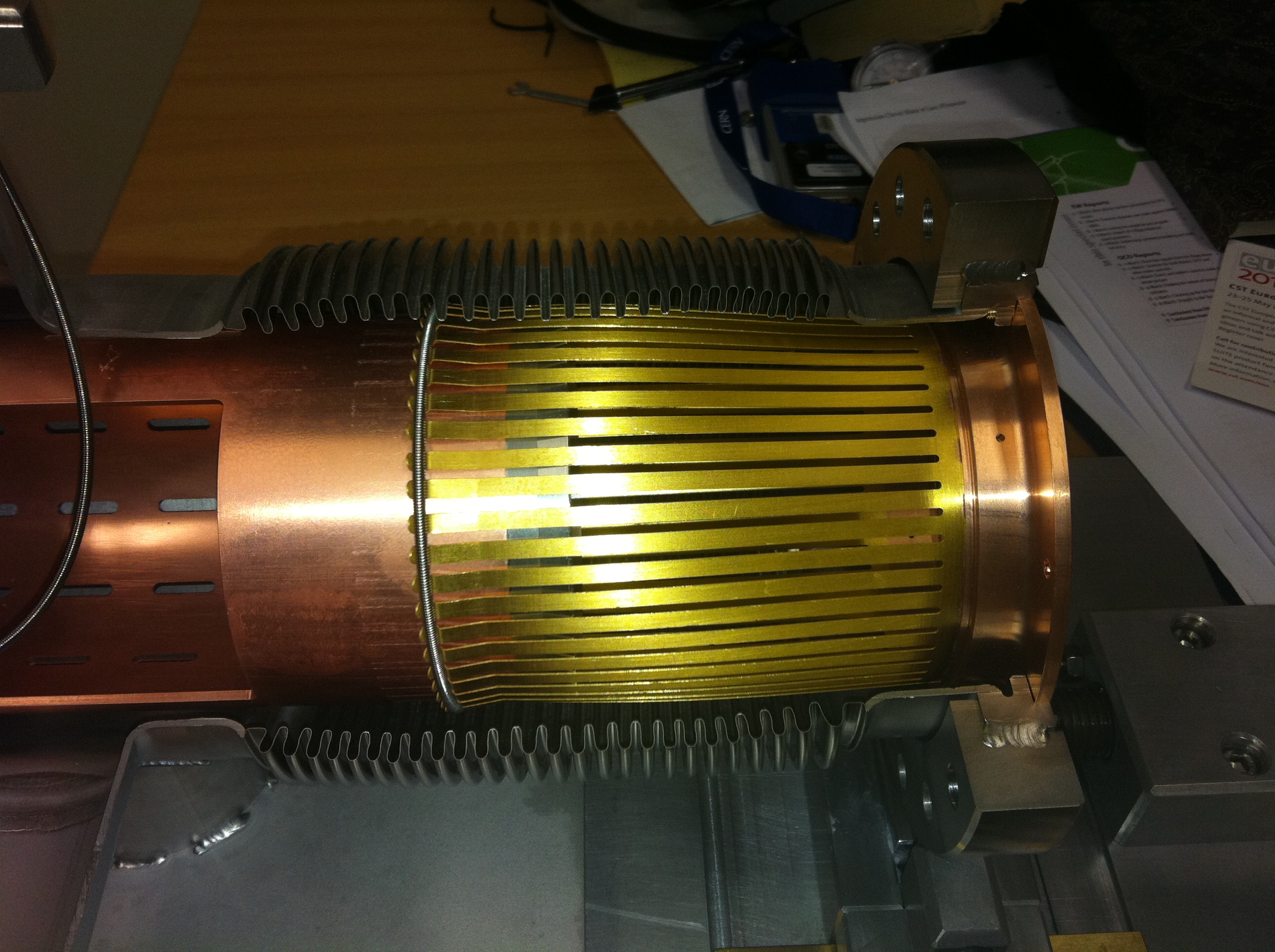
- Mock up of a VMAAA module available in HD's office => See for instance pictures 1 and 2. Plan to perform bench impedance measurements on this type (instead of VMABA initially discussed). Possibility to compress or elongate it and to move it laterally.
- OK is doing impedance simulations with HFSS checking the strange low-Q values that BS mentioned previously.
- WW is preparing a new bellow for MKI.
- What is the power dissipated on the spring?
- MKI RF fingers will be in SS due to 350 deg i.e. much higher => Have to go to SS instead of Cu Be.
2) What was wrong with the Plug-In Modules (PIMs) in the cold part of LHC? (Pierre Strubin): pptx
- Pierre led the vacuum group at the time of the vacuum group crisis.
- Will mainly focus on the mechanical aspects.
- What is the maximum stroke?
- Some key dimensions, what does a PIM look like and what happened in August 2007? => After warm-up of sector 7-8, abuckled PIM was discovered in interconnect QQBI.26.R7. Was really found by chance!
=> Was rapidly discovered to be due to a non-conformity during the manufacturing: bending angles out of tolerance. The angle should have been 12 deg.
- There was a constraint of ~ 30 mOhm / RF finger or something like this with a total of 0.1 mOhm.
- At BINP, it was decided in the back of their management to change the geometry to meet the DC contact resistance value.
- The pb came from the fact that the height at the tip of the RF finger was not good (4 mm instead of 6.5), then the contact force was not good then they modified the angle from 12 to 19 deg and even found as high as 45 deg => On average it was ~ twice the nominal value. See nice picture from Pierre (slide 7).
- Local anomalies => Length of interconnects sometime at the limit of acceptable.
- Furthermore, the length of interconnects sometime at the limit of acceptable => Cedric Garion is following all that. 2 critical ones and the 2nd one is believed to have changed (tbc).
- ANSYS simulation: Very nice movies for a conforming PIM and a faulty PIM. Many simulation studies by Delio and also measurements done in the lab.
- Sergio measured the friction coefficient and was found it to be correct.
- The WG was then dormant until the incident in 2-3.
- Impact on resistance? A buckled finger may loose contact when warmed-up:
- There is a plastic deformation for 16 mm and a possible subsequent bad contact.
- Increasing the T to 150 deg leads to stroke of ~ 10 mm, which was judged to be ~ the limit.
- At 10 mm we consider it is OK but at 16 mm not. Reminder: this is for a non-confirming RF finger (it depends on the angle and it was studied for the worst case, i.e. largest angle).
- Reminder: 1.2 N is what SC remember on the required force needed for a good contact and we see here that ~ 0.5 are obtained for a stroke of ~ 10 mm.
- In LS1 we will have a complete warm up and might have pbs with the buckling.
- Corrective actions:
- A tooling was designed to restore the correct geometry of the fingers => Back to conforming PIM (both angle and 6.4 mm at the tip).
- Move the SSS by 2 mm to reduce the span of the QQBI => The stroke is smaller (we have gain 2 mm in the stroke) => Answer to 1 action we had.
- Means of detection of damaged PIMS:
- with an RF transmitter, pushed by a draft (2 m/s through the sector).
- Lyn: for the 1st time in the machine the BPM were working before the beam as we needed them for the RF ball.
- FritzC proposed to use the X-ray tomogaphy. It was designed to be used in the arcs, and at cold. For instance we cannot use it for the experiments.
- Follow-up after 2008:
- Finding ways to repair a broken PIM without global warm up
- Limit the warming up to one half-cell.
- Use neon flushing to prevent condensation of gas in beam tube.
- Analyse and mitigate risk at the extremity of the arcs
- Minimise the warm up during long cryogenic stand-by periods.
- Analyse the situation in the stand-alone magnets.
- Related problems after the 3-4 incident
- Debris in the beam pipe and PIMs (could affect resistance).
- Buckling of the nested bellows.
- Strategy of PIM replacement.
- Summary:
- The PIM problem was purely mechanical
- It has been fully understood.
- Non conforming PIMs can be repaired.
- Strategy for replacement has been defined and is applied.
- With some accrobacy, a PIM can even be replaced in a cold sector (only partial warm up of one cell).
- A repaired PIM has a DC resistance as specified => RF measurements were also made end 2008 and beginning 2009.
- We still have this "epee de Damocles" each time we will do a warm up we can have a buckling effect.
- Strategy in LS1 => Ball after the run and before the run.
- Maximum stroke => see table 8, maybe ~ 40 mm.
- How many variants of the PIMs? There should be 3: QQBI more sensitive, QBQI and QBBI + some variants for standalone magnets.
- Note given by Delio from Pierre.
3) Actions to be taken for the next meeting
- Old actions.
4) Miscellaneous
- The next (6th) meeting will take place on 24/04/2012 between 09:00 and 11:00 (max.) in room 6-R-018 => Agenda:
1) Equipment review: some equipments from BE/BI (RJ or RV).
- See preliminary agendas for the next meetings.
Minutes by E. Metral, 24/05/2012.